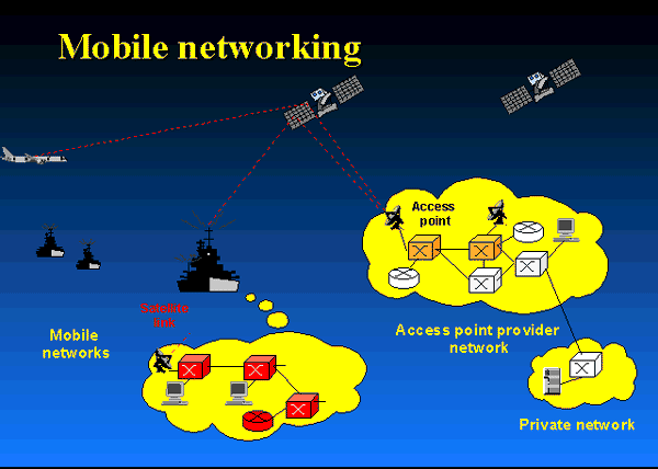
Heterogeneous Networks
Future Heterogeneous
Communications Networks
____________________________________________________________________________________________________
MIMO Free Space
Optical Communications using Multiple Light Beams Propagation through
Atmospheric Turbulence
Free space optical communication (FSOC) is a promising technology
for high bandwidth wireless communication links over a long distance where a
fiber or wire is unfeasible or where RF communication is inadequate. The link
performance of FSOC can be severely degraded by atmospheric turbulence induced effects including intensity
fluctuations, phase fluctuations, beam wandering
and beam jittering. Atmospheric turbulence strength would become stronger with
increasing Rytov variance related to
the
refractive index structure
parameter Cn2 and
the
propagation distance L.
Under the strong turbulence regime, scintillation index increases beyond unity,
reaches its maximum value in the focusing regime and decreases toward unity in
the saturation regimes. Recent experiments have shown significant deviations
from the Kolmogorov model in some layers of the atmosphere, which has prompted
research on
optical wave propagation through
non-Kolmogorov atmospheric turbulence.
The intensity
fluctuations or scintillation at the receiver reduces FSOC
channel capacity. In order to improve system performance, scintillation can be
mitigated by means of reducing
the
spatial coherence of the transmitted
beam and the
spatial diversity using multiple
transmitted beams and multiple receivers.
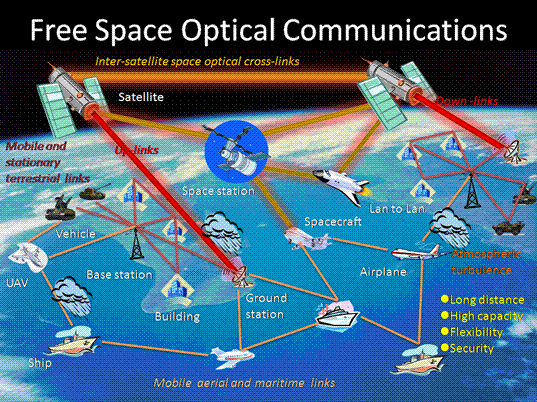
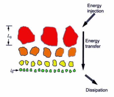
Fig.-1.
Free Space Optical Communications
Partially coherent beams with reduced spatial coherence show
lower scintillation at the cost of larger divergence angle and lower average
received power. Partially coherent beams have a lower scintillation than fully
coherent beams. However, a partially coherent beam has a larger beam spreading
and forms a large spot in the receiver aperture, which leads to a loss of the
transmitted energy being received by the detector. By
optimizing
the spatial coherence length, the
improvement in scintillation reduction
can
overcome the penalty of power reduction and significant
signal-to-noise ratio gains can be obtained in weak atmospheric turbulence.
Spatial diversity using multiple transmitted beams and multiple
receivers can also be employed to reduce scintillation and ultimately improve
FSO channel capacity. It has been shown that the scintillation of a beam array
can be reduced by carefully adjusting the spatial separation of beamlets.
However, scintillation of a beam array will increase significantly if the
spatial separation of beamlets is smaller than the correlated length. In
addition, the received energy from
the
beam arrays is low unless the constituent beamlets are inclined
to overlap at the receiver aperture, which is difficult to achieve over long
propagation distances. The use of multiple transmitters and receivers has also
been suggested for
use in multiple-inputmultiple-output (MIMO) configurations.
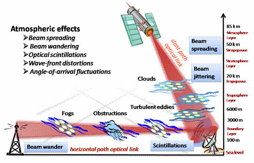
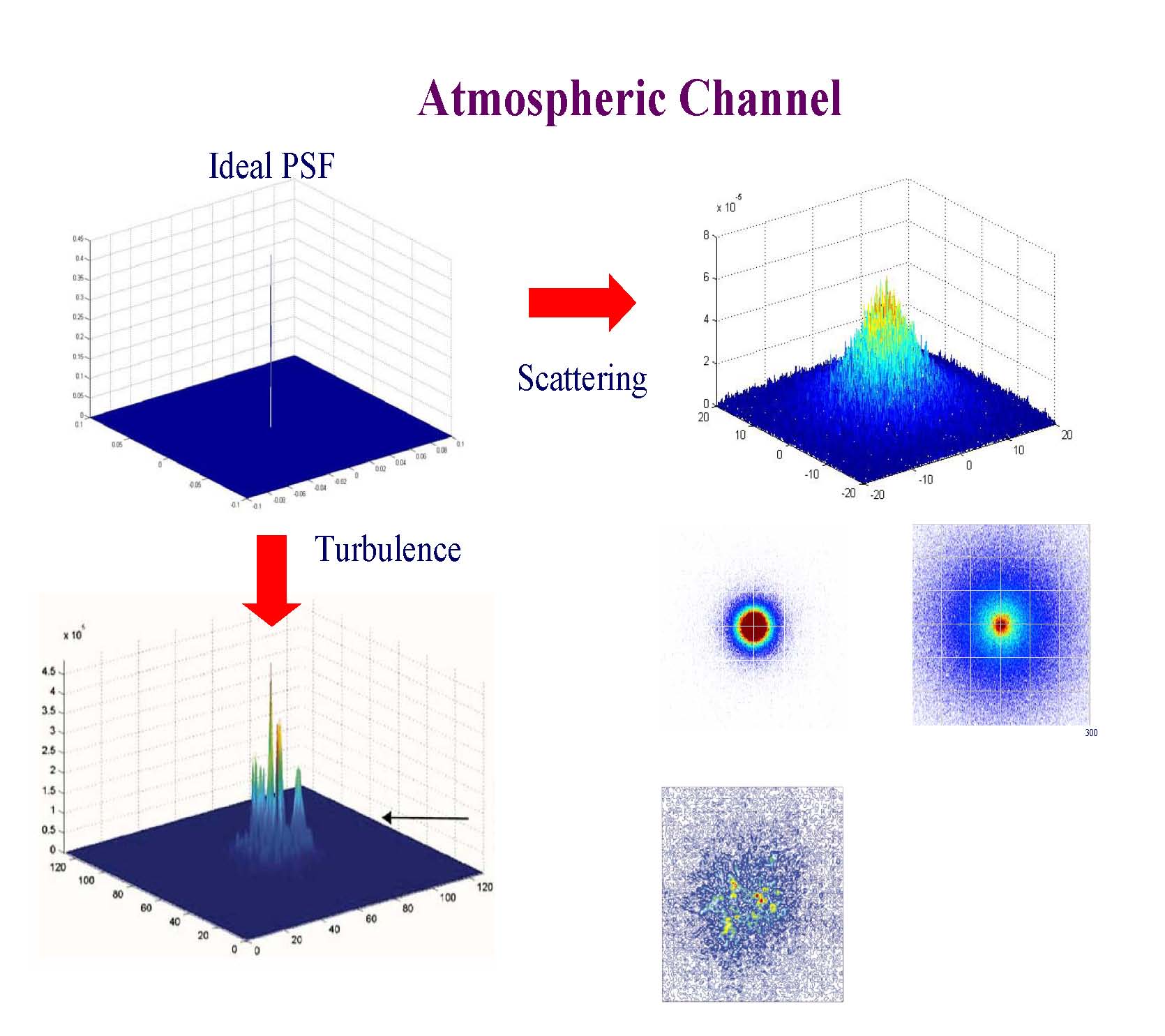
Fig.-2.
Atmospheric effects on Free Space optical communications
Typically FSOC
receiver employs the acquisition, tracking and pointing (ATP) mechanism to point
the receivers narrow field of view (FOV) at the small divergence transmitted
beam. This approach is impractical for many mobile applications requiring small
size and low weight, so a wide FOV optical receiver is needed to eliminate the
large, gimbals based mechanism.
As shown in Fig 3(a), a
wide FOV receiver can be achieved by using a single-element fisheye lens group
to collect the wide field beam, and a steering mirror to couple the beam into a
multi-mode fiber.
Professor Joseph Kahn of
Stanford University and Mr.
Djahani, in an overview paper
entitled; Imaging
Diversity Receivers for high-Speed Infrared Wireless Communication,
[2] describes these contributions as:
·
Implementation of multi-branch angle diversity using
non-imaging elements requires a separate optical concentrator for each receiving
element, which may be excessively bulk and costly. Yun and Kavehrad proposed the fly-eye
receiver [1], which consists of a
single imaging optical concentrator (e.g., a lens) that forms an image of the
received light on a collection of photo-detectors, thereby separating signals
that arrive from different directions. In this article, we refer to this design
as an imaging angle-diversity
receiver, or simply an imaging
receiver. Implementation of an angle-diversity receiver using imaging optics
offers two advantages over a non-imaging implementation. First, all
photo-detectors share a common concentrator, reducing size and cost. Second, all
the photo-detectors can be laid out in a single planar array, facilitating the
use of a large number of receiving elements or pixels.
·
In non-Line-of-Sight (LoS) wireless optical links, Yun and
Kavehrad [1] also proposed the spot-diffusing
transmitter, which utilizes multiple narrow beams pointed in different
directions, as a replacement for the conventional diffuse transmitter, which
utilizes a single broad beam aimed at an extended reflecting surface. In this
article, we refer to the spot-diffusing transmitter as a multi-beam or quasi-diffuse
transmitter. While the diffuse transmitter provides considerable immunity
against beam blockage near the receiver, it yields a high path loss. The
quasi-diffuse transmitter is expected to reduce path loss compared to the
diffuse transmitter, because the narrow beams experience little path loss
traveling from the transmitter to the illuminated reflective surfaces.
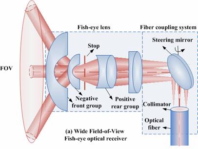
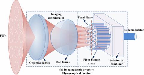
Fig.-3. Wide field-of-view
diversity optical receivers for free space optical communications
Compared with the single input single output FSOC system, we
investigate BER performance of wide FOV diversity optical receiver of Multiple
Input Multiple Output (MIMO) FSOC for laser beam propagation through
moderate-strong atmospheric turbulence.
Figure
4(a) shows BER performance of various MIMO FSOC systems as a function
of SNR after 1000
m propagation through strong
turbulence. The results demonstrate a significant decrease in BER as the number
of diversity transmitters/receivers is increased. The results shown in Figure
4(b)
for BER as a function of distance reveals the BER approaches to the maximum at
distance of 1500
m and diversity receivers reduce
the BER performance over long distance, as diversity apertures average out the
scintillations of multi-beams with decreasing coherent length in strong
turbulence. For more details, see references [3] through [5].
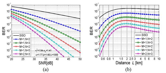
Fig. 4(a) BER versus SNR for SISO and MIMO FSOC, (b) BER vs transmission
distance for SISO and MIMO FSOC
1.
1.
G.
Yun, M. Kavehrad, "Spot-Diffusing and Fly-Eye Receivers for Indoor Infrared
Radio Communications," IEEE Int. Conf. on Selected Topics in Wireless
Communications, Vancouver, June 1992.
2.
Joseph Kahn, et al., Imaging Diversity Receivers for high-Speed Infrared
Wireless Communication, IEEE Communications Magazine, Vol. 36, No. 12, pp.
88-94, December 1998.
3.
P.
Deng, M. Kavehrad, Z. Liu, Z. Zhou, and X. Yuan, "Capacity of MIMO Free
Space Optical communications using multiple partially coherent beams propagation
through non-Kolmogorov strong turbulence," Opt. Express 21(13),
15213-15229, 2013.
4.
P.
Deng, X. Yuan, M. Kavehrad, M. Zhao and Y. Zeng, "Off-axis catadioptric
fisheye wide field-of-view optical receiver for free space optical
communications," Optical Engineering 51(6), 063002, 2012.
5.
P.
Deng, M. Kavehrad and X. Yuan, "Comparing Wide Field-of-View Optical
Receivers for Free Space Optical Communications," in The IEEE Photonics
Society 2012 Summer Topical Meetings, Seattle, 2012.
____________________________________________________________________________________________________
Propagation of Radial Airy Array
Beams through Atmospheric Turbulence
The array beams, constructed by combining multiple separate
beamlets, have attracted much attention due to their wide applications to
technical areas such as
high-power
laser systems,
free-space optical communications,
active optical imaging systems, etc. Up to now, the propagation properties of various types of array
beams, such as the linear, rectangular and radial ones, in free space or in
atmospheric turbulence have been investigated in detail. Meanwhile, many special
beam types with various transverse intensity profiles, e.g., the elliptical
Gaussian, Hermite-Gaussian, circular dark hollow and flat-topped beams, were
considered as the beamlets of the array beams.
Recently, several authors have addressed the propagation
properties of Airy beams in atmospheric turbulence,
showing that the Airy beams
are more resilient against turbulence-induced perturbations than the
conventional Gaussian
ones. This fact implies that
Airy beams have the
potential
for
offering
some advantages if they are used in applications involving beam propagation in
atmospheric turbulence. Hence, it is interesting to develop an array beam by
combining multiple Airy beamlets.
The average
intensity
distribution of an Airy
array beam is an important quantity
in practice.
To deeply understand the average-intensity-distribution evolution of Airy array
beams passing through atmospheric turbulence, the theoretical formulations of
their average intensity are
desirable.
In practice, two types of beamlet combination are usually
considered.
One is the phase-locked combination, and the other is the non-phase-locked
combination. In this
project, we first formulated
the average intensity of both phase-locked and non-phase-locked radial Airy
array beams propagating in atmospheric turbulence, and then examined the average-intensity-distribution evolution of these array
beams in atmospheric turbulence in
sufficient
details.
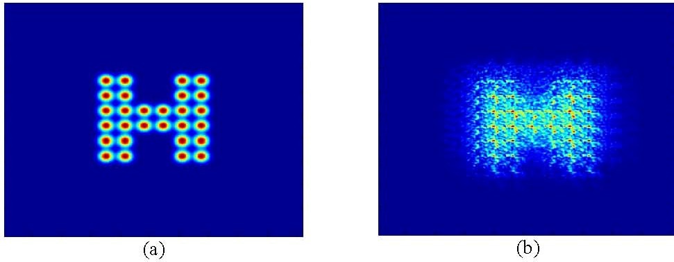
We have considered that a radial
Airy array beam, which consists of N equal off-axis Airy beamlets situated
uniformly on a ring as shown by an example of N = 4 in Fig. 1, propagates along
the positive z-axis in atmospheric turbulence.
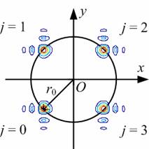
Fig. 1. Schematic illustration
of a radial Airy array beam constructed by four equal off-axis beamlets.
The evolution of the normalized
average intensity along the 45º axis in the x-y plane of a single
Airy beam during propagation in both free space and atmospheric turbulence is
illustrated by Fig. 2.
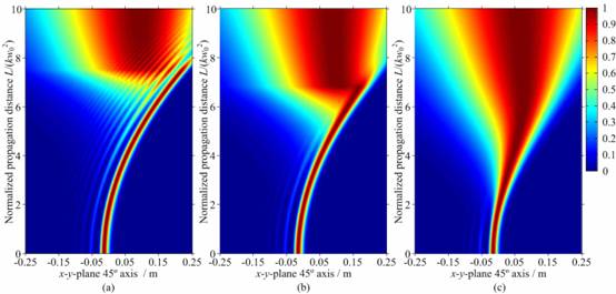
Fig. 2. The evolution of the
normalized average intensity along the 45º axis in the x-y plane
of a single Airy beam during propagation in both free space and atmospheric
turbulence, where the normalization is obtained by scaling the average intensity
at a certain propagation distance by its highest value at that propagation
distance. λ
= 1550 nm. (a) Cn2 = 0; (b) Cn2
= 10−15 m−2/3; (c) Cn2
= 10−14 m−2/3.
The transverse average intensity
patterns of phase-locked Airy array beams propagating in both free space and
atmospheric turbulence are shown by Fig. 3.
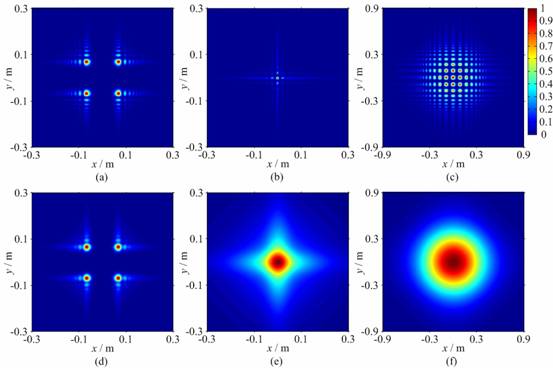
Fig. 3.
Transverse average intensity patterns of phase-locked Airy array beams
propagating in both free space and atmospheric turbulence, where λ = 1550
nm, N = 4 and tx = ty = 66 mm. (a)
L = 1 km, Cn2 = 0; (b) L = 3 km, Cn2
= 0; (c) L = 8 km, Cn2 = 0; (d) L = 1
km, Cn2 = 10−14
m−2/3; (e) L = 3 km, Cn2 = 10−14
m−2/3; (f) L = 8 km, Cn2 = 10−14
m−2/3.
The
transverse average intensity patterns of non-phase-locked Airy array beams
propagating in both free space and atmospheric turbulence are shown by Fig. 4.
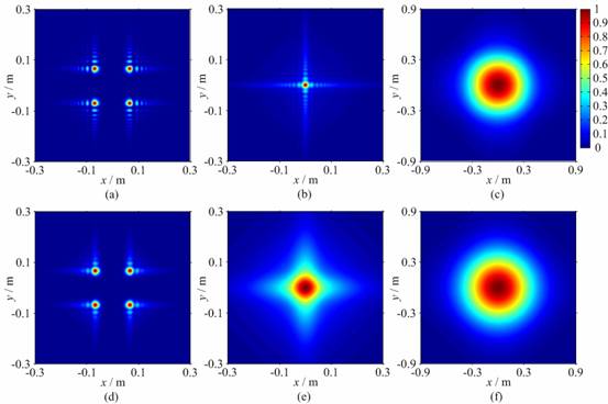
Fig. 4. Transverse average
intensity patterns of non-phase-locked Airy array beams propagating in both free
space and atmospheric turbulence, where λ = 1550 nm, N = 4 and
tx = ty = 66 mm. (a) L = 1 km, Cn2
= 0; (b) L = 3 km, Cn2 = 0; (c) L = 8
km, Cn2 = 0; (d) L = 1 km, Cn2
= 10−14 m−2/3; (e) L
= 3 km, Cn2 = 10−14
m−2/3; (f) L = 8 km, Cn2 = 10−14
m−2/3.
The
longitudinal cross-section average intensity distributions of phase-locked Airy
array beams with varying Airy-beamlet parameters are illustrated by Fig. 5.
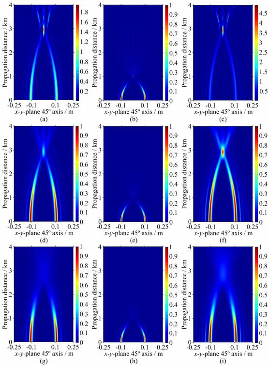
Fig. 5. Longitudinal
cross-section average intensity distributions of phase-locked Airy array beams
with varying Airy-beamlet parameters, where λ = 1550 nm, N = 4,
tx = ty = 66 mm. (a) Cn2
= 0, w0 = 12 mm, a = 0.1; (b) Cn2
= 0, w0 = 6 mm, a = 0.1; (c) Cn2
= 0, w0 = 12 mm, a = 0.05; (d) Cn2
= 10−15 m−2/3, w0
= 12 mm, a = 0.1; (e) Cn2 = 10−15
m−2/3, w0 = 6 mm, a = 0.1; (f) Cn2
= 10−15 m−2/3, w0
= 12 mm, a = 0.05; (g) Cn2 = 10−14
m−2/3, w0 = 12 mm, a = 0.1; (h) Cn2
= 10−14 m−2/3, w0
= 6 mm, a = 0.1; (i) Cn2 = 10−14
m−2/3, w0 = 12 mm, a = 0.05.
The
longitudinal cross-section average intensity distributions of non-phase-locked
Airy array beams with varying Airy-beamlet parameters are shown by Fig. 6.
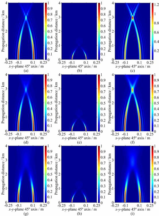
Fig. 6. Longitudinal
cross-section average intensity distributions of non-phase-locked Airy array
beams with varying Airy-beamlet parameters, where λ = 1550 nm, N =
4, tx = ty = 66 mm. (a) Cn2
= 0, w0 = 12 mm, a = 0.1; (b) Cn2
= 0, w0 = 6 mm, a = 0.1; (c) Cn2
= 0, w0 = 12 mm, a = 0.05; (d) Cn2
= 10−15 m−2/3, w0
= 12 mm, a = 0.1; (e) Cn2 = 10−15
m−2/3, w0 = 6 mm, a = 0.1; (f) Cn2
= 10−15 m−2/3, w0
= 12 mm, a = 0.05; (g) Cn2 = 10−14
m−2/3, w0 = 12 mm, a = 0.1; (h) Cn2
= 10−14 m−2/3, w0
= 6 mm, a = 0.1; (i) Cn2 = 10−14
m−2/3, w0 = 12 mm, a = 0.05.
__________________________________________________________________________________________________
Network-Enabled RF/Optical Wireless Communications
-
Wavelet Packet
Transmission Systems
As proven by the success of OFDM,
multi-carrier modulation has been recognized as an efficient solution for
wireless communications. Waveform bases other than sine functions could
similarly be used for multi-carrier systems in order to provide an alternative
to OFDM. For example, wavelet packet modulation (WPM) for transmission over
wireless channels, is shown to be overall quite similar to OFDM, but with some
interesting additional features and improved characteristics.
Though the principle of
multi-carrier modulation is not recent, its actual use in commercial systems had
been delayed until the technology required to implement it became available at
reasonable costs. Similarly, the idea of using more advanced transform than
Fouriers as the core of a multi-carrier system has been introduced more than a
decade ago. However, such alternative methods have not been viewed with major
interest and therefore have received little attention. With the current demand
for high performance in wireless communication systems, one is entitled to
wonder about the possible improvement that wavelet-based modulation could
exhibit compared to OFDM systems.
Several objectives motivate the
current research on WPM. First, the characteristics of a multi-carrier modulated
signal are directly dependent on the set of waveforms of which it makes use.
Hence, the sensitivity to multi-path channel distortion, synchronization error
or non-linear amplifiers might present better values than a corresponding OFDM
signal. Little attention has been given to the evaluation of those system level
characteristics in the case of WPM. Moreover, the major advantage of WPM is its
flexibility. This feature makes it eminently suitable for future generation of
communication systems. With the ever-increasing need for enhanced performance,
communication systems can no longer be designed for average performance while
assuming channel conditions. Instead, new generation systems have to be designed
to dynamically take advantage of the instantaneous propagation conditions. This
situation has led to the study of flexible and reconfigurable systems capable of
optimizing performance according to the current channel response. A tremendous
amount of work has been done recently to fulfill this requirement at the
physical layer of communication systems: complex equalization schemes, dynamic
bit-loading and power control that can be used to dynamically improve system
performance. While WPM can take advantage of all those advanced functionalities
designed for multi-carrier systems, it benefits also from an inherent
flexibility. This feature together with a modular implementation complexity
makes WPM potential candidate for building highly flexible modulation schemes.
Wavelet theory has been foreseen by many investigators as a good platform on
which to build multi-carrier waveform bases.
- Network-Enabled
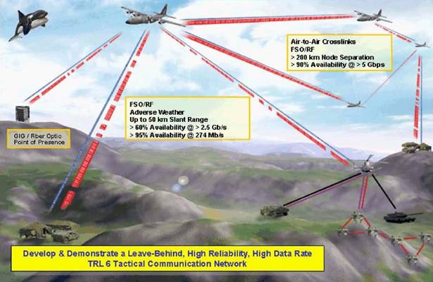
RF/Free Space Optical (FSO) Communications
Needless to say, where line-of-sight is available (see the figure
below), using ultra-short laser pulses, one may achieve the ultimate wideband
over unregulated optical frequency bands, using Free-Space-Optical (FSO) or a hybrid
of RF/FSO links. Then one is able to beam optical band to distant points. This
approach could help bring optical bandwidth, capable of carrying huge amounts
of information, to applications ranging from wireless communications between
air and ground vehicles on the battlefield, to short links between college
campus buildings or to metropolitan area networks that connect all the
buildings in a city.
The papers below are based on a
recently devised new methodology (Patent) to pack the data into rapid-fire bursts of light that can blast
through fog and clouds. This new system uses ultra-short pulses of laser light
that provide greater bandwidth and improved reliability over conventional
optical wireless links. The approach uses a technique called "Fractal
Modulation", which is a form of Wavelet Packet Modulation (WPM), to
produce wavelets that can co-exist in a signal channel without interference,
and provide frequency and time diversity, concurrently. By sending the same
message at several different rates (multi-rate), one can get through adverse
weather conditions.
Using Fractal modulation, each receiver has a menu to
choose the best received signal transmission rate, thus adaptation is
feed-forward. At the same time, wavelets
have the desirable properties of being both time and frequency limited, thus
are able to pack a large amount of power in very short pulses, in addition to
providing inherent diversity:
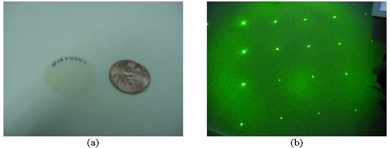
- A 100
fs pulse at 100 mJ would produce a peak power of 1 Terawatt. At 2 Giga
pulse per second, this is 200 Mega Watts of average power. With today’s nano-second
technology, a Terawatt of peak power would require laser energies of 1000
J.
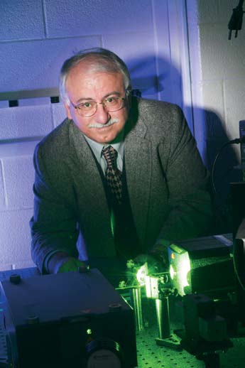
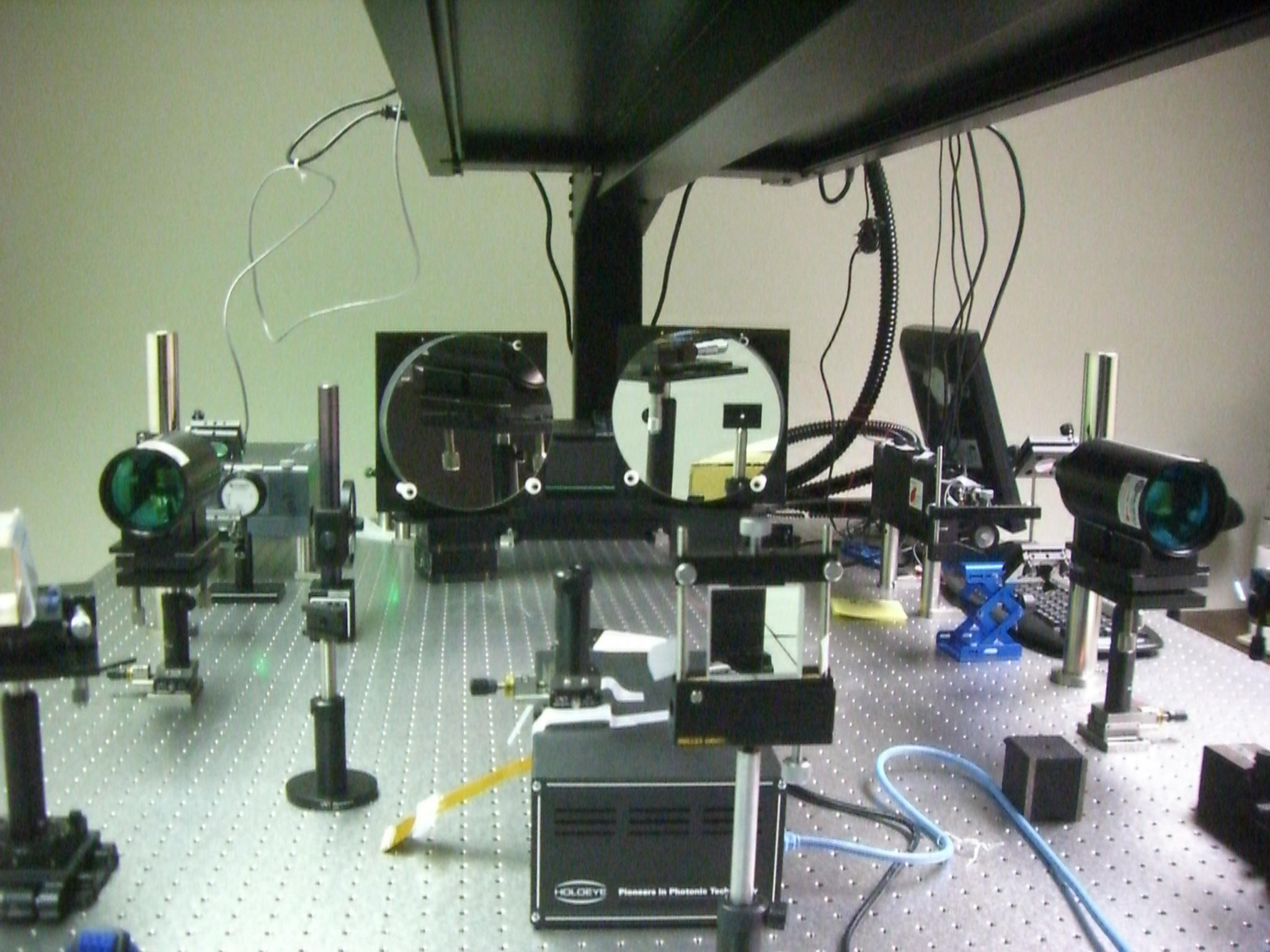
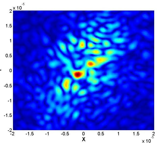
Ultra-short Pulse Shaping Experimental
Set-up
(CICTR LABS)
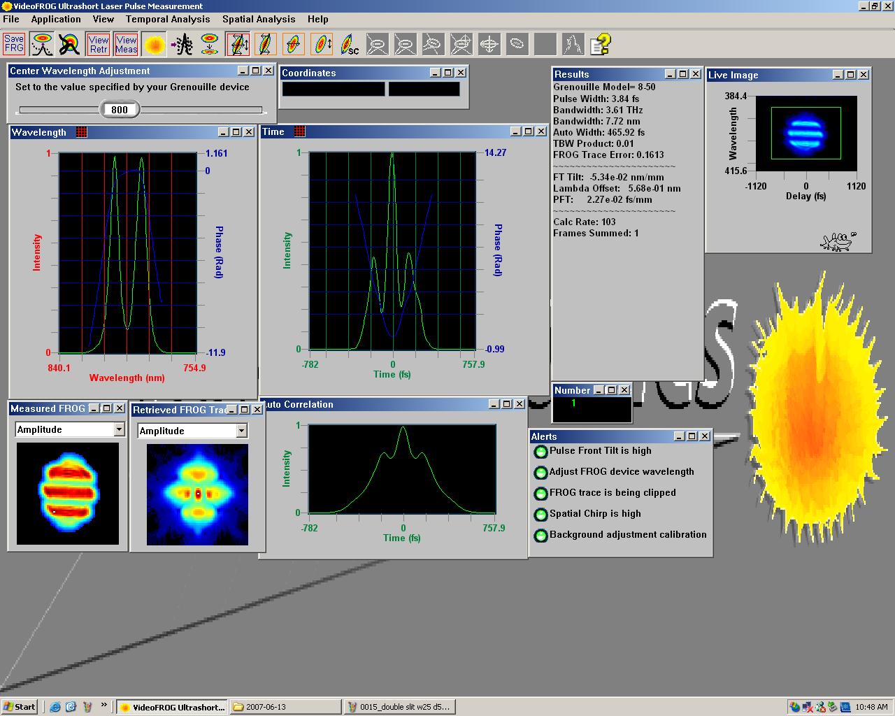
Real-Time 460 Femto-second Meyer Wavelet
Shaped Pulse at a 3 Giga Pulse per Second Rate
(Intensity Correlation Image at CICTR
LABS)
Spatial and temporal matched filtering
can then be applied through Spectral Encoding and Decoding of frequency
components of the broadband ultra-short light pulses. The encoding/decoding may
be realized all-optically through photolithographic masks or other types of
spatial light modulators.
The space-time focusing properties of
this approach can lead to a new class of wireless “Opportunistic
Communications” systems with significant advantages over current
RF approaches. Using this approach, one is liberated from the many constraints
of spectrum allocation and regulation. The spatial focusing potential of this
approach is an appealing quality, in power saving and would allow accommodating
as many users as possible within it. Interference issues of shared RF bands are
non-existent here.
Potential applications include commercial wireless as
well as specialized systems, such as secure communication systems that demand a
low probability of intercept.
See also; DARPA ORCLE.
-
S. Lee and M. Kavehrad,Airborne Laser
Communications with Impulse Response Shortening and Viterbi Decoding,
Proceedings of the IEEE MILCOM, Washington,
D.C., October 2006.